Conductive PVC Technical Guide
Single-Sided vs Double-Layer Conductive PVC Film: Interface Design Checklist
Compare single-sided conductive PVC and double-layer conductive/insulating PVC by functional surface, test setup, assembly interface and qualification need.
Published: September 30, 2026 · Author: Technical Editorial Team
Article summary
Compare single-sided conductive PVC and double-layer conductive/insulating PVC by functional surface, test setup, assembly interface and qualification need.
Technical content
Single-Sided and Double-Layer Conductive PVC Film: Choosing by Interface Design
The supplied product documents distinguish a single-sided conductive PVC film from a double-layer PVC construction described as conductive/insulating. Their selection should be driven by the electrical interface drawing, not by a general assumption that two layers are better than one.
Start with the functional surfaces
For a single-sided film, identify the surface that must contact the counterpart component and the path required for continuity. For a double-layer film, identify the conductive face, insulating face, edge treatment, fastening method and any locations where the layer boundary must remain protected. The product data alone does not define those interfaces.
| Design question | Single-sided conductive film | Double-layer conductive/insulating film |
|---|---|---|
| Surface role | One designated conductive surface must be identified in the assembly. | The drawing must identify conductive and insulating functions and avoid ambiguity at edges or cut-outs. |
| Supplier-reported surface resistance | 120 Ω ±30% in the supplied workbook for 0.75 mm and 1.0 mm variants. | 100 Ω ±30% in the supplied workbook for 0.75 mm and 1.0 mm variants. |
| Mechanical data | Variant values in the workbook should be reviewed for the actual thickness. | Do not assume the same tensile/elongation values as the single-sided construction. |
| Acceptance test | Define electrodes and test the functional surface. | Define which face is measured and how layer integrity or isolation is evaluated. |
| Qualification need | Confirm contact resistance and service environment in the finished assembly. | Confirm continuity and isolation behavior in the finished assembly. |
Interpret the supplied values correctly
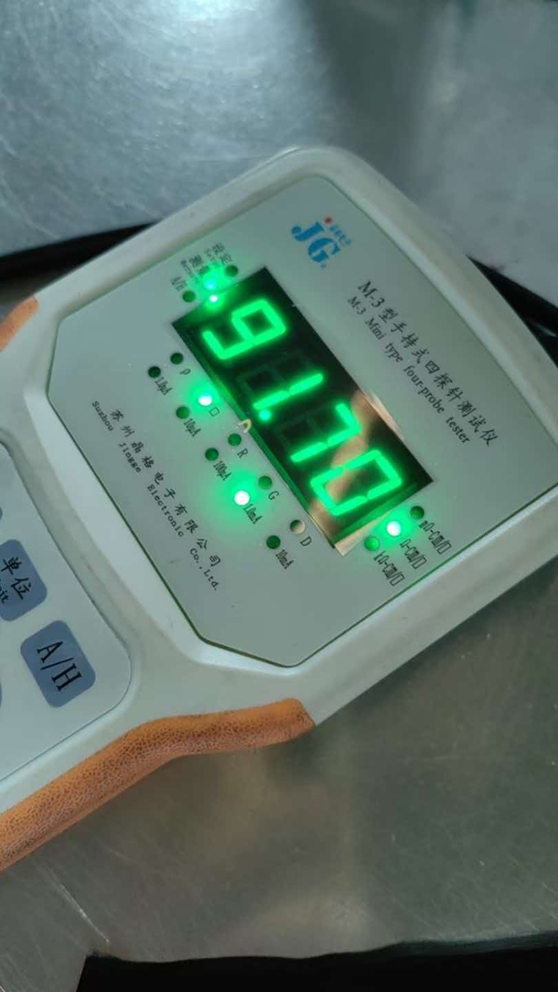
The supplier spreadsheet lists the single-sided and double-layer values against GB/T 1410. A surface-resistance figure is sensitive to configuration and environment. It should therefore be inserted into the purchase specification together with its unit, method edition, test voltage, time, electrodes, conditioning, sample size and acceptance rule.
Assembly details that should not be omitted
Specify cut dimensions, tolerances, contact pads, edge sealing or coverage, fastener locations, joining process, handling precautions and any required bending or environmental exposure. If conductive film is used near electronic equipment, the design owner should also determine whether contact resistance, shielding, grounding, insulation coordination, flammability or reliability testing is required. These are application-level requirements, not claims made by the basic film data sheet.
Sampling and approval
Before a production order, obtain a representative sample of the selected thickness and construction. Test it with the actual counterpart material and proposed contact geometry. Record the result using the agreed procedure. Approve the drawing and quality plan before defining an acceptance range. Repeat that check when material construction, thickness, lot, processing or operating envelope changes.
References
- [GB 12952-2011 — Polyvinyl chloride plastic sheets for waterproofing](https://www.chinesestandard.net/PDF.aspx/GB12952-2011). This is a PVC waterproofing-sheet standard; it is not a certification claim for every conductive film configuration.
- [GB/T 1410-2006 — Methods of test for volume resistivity and surface resistivity of solid electrical insulating materials](https://www.chinesestandard.net/PDF.aspx/GBT1410-2006). The referenced publication notes that it has been replaced by GB/T 31838.2-2019; use the contractual project edition and the complete method when testing.
- [ASTM D257-14(2021)e1 — DC Resistance or Conductance of Insulating Materials](https://www.astm.org/d0257-14r21e01.html). The ASTM scope notes that the method is not suitable for moderately conductive materials; suitability must be confirmed for the selected material and target range.